Time:2021-12-01Views:
Brief introduction to Gerber file of PCB factory
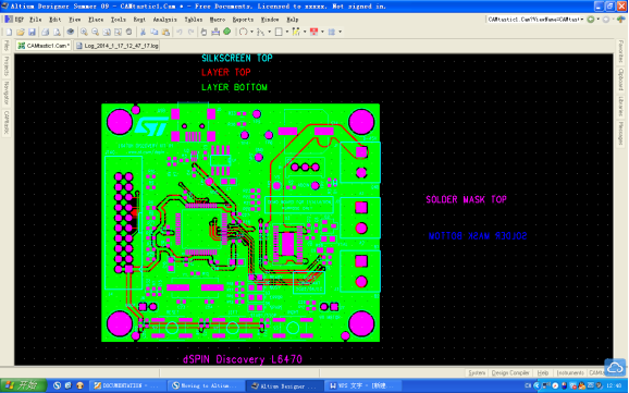
Gerber files are one of the important file formats used in circuit board design and PCB fabrication data. The files were originally developed by Gerber Systems Corp, a subsidiary of Gerber Scientific. It describes the features of the board, such as many solder mask layers, conductor layers, legends, drilling data, etc.
Typically, PCBs are designed on a specialized electronic design automation (EDA) or a computer-aided design (CAD) system that utilizes manufacturing data to create a two-dimensional or three-dimensional design of the PCB. Data needs to be entered into these systems to produce these designs. This sounds easy because one would think of it as a system that automatically generates designs as data is entered. But this is not true because the user has to refer to the guidelines and references mentioned in the Gerber document when entering data. Gerber documents were developed to detail the requirements for each phase of product development. These files are used in both PCB manufacturing and PCB assembly processes.

Introduction to 4 Important Features of Gerber Files
Gerber files follow the ASCII vector format and provide the following information:
l Configuration parameters
l Macro and aperture size
l Drawing and flash command codes
l XY coordinate position of draw and flash commands
There is a Gerber file for each drill range and image layer of the board. These files are archived in one file and sent to the printed circuit board manufacturer. Occasionally, a PCB manufacturer may receive more than eight standard two-layer PCB files, or even more. They may include the following:
l An image of the copper traces will be included on the bottom of the PCB.
l An image of the copper traces will be included on the top of the PCB.
The same is that there will be two files for the solder mask and the silkscreen image, applied to the bottom and top of the PCB, respectively. There will be documentation indicating several drill holes, the location and purpose of the drill holes. Many times, surface mount and plated through holes are noted in separate documents. There will be a detailed outline of the circuit board describing the machining process to be carried out, the internal cuts to be made, etc. Also, there is a file called README which explains what the above files are for.
A brief introduction to the different types of Gerber file formats
The following are two popular Gerber file formats:
l Rs-274-D:This is the oldest Gerber file format designed by Gerber Systems Corp. The file is represented in Numerically Controlled (NC) format and is compatible with various photoplotters used in the 1970s. This format had a number of drawbacks that eventually led to its withdrawal in 2014. This format is called Standard Gerber.
l X-Gerber's RS-274-X: This Gerber file format has been used since 1998, which uses interpretable ASCII commands. These commands are combined to create 2D vector graphics. It is also known as Extended Gerber.
l Gerber X2:This format is designed for most advanced CAM software applications.
Gerber files can be easily generated using several software applications such as Altium Designer, Cadence, EAGLE, etc. If you don't have any of these software applications, you can turn to XCF FPCB manufacturers for help. We'll help you create a Gerber file from scratch.

